ASCO
 Series 4000
Plus Options

- Detailed
Description - Priced
Packages - Priced
Options - Detailed
Specifications - Technical
Summary - Model
Features - Lease
Purchase - Product
Families - Product
Finder - Transfer
Switches
-
Detailed Description
ASCO Series 4000 Transfer Switch Group - Automatic Transfer Switches - Enclosed & Open
As the world leader in emergency and standby power transfer solutions, ASCO keeps your power on. ASCO Automatic Transfer Switches and Power Systems safeguard data and telecommunications networks, industrial processes and critical installations from health care facilities to financial transaction centers.
Over the past 70 years, ASCO has pioneered every major product innovation in power transfer technology. ASCO is committed to providing a full range of quality-driven products, backed by 24-hour nationwide service support.
ASCO Series 4000 Enclosed- ASCO Series 4000 automatic transfer switches are suitable for emergency and standby power system applications. Manual switches are also available for the same price as shown for automatic with a deduction of $150 per unit.
ASCO Series 4000 Open - ASCO Series 4000 automatic transfer switches are suitable for emergency and standby power system applications. These units are identical to Series 4000 enclosed but do not have front covers or doors. This Series is designed to be installed inside rack systems or other enclosures and will not meet electrical or UL codes if installed standing alone.
Sizes 150 through 3000 amps in a compact design with 2, 3, & 4 pole configurations. Available 120 to 600 VAC. UL 1008 listed to 480 VAC for total system loads. True double-throw, inherently interlocked construction to absolutely prohibit connecting both sources together. Mechanically held, electrically operated utilizing a reliable, field-proven single solenoid operator. Contacts easily accessible for easy inspection and preventive maintenance. Meets National Electric Code requirements (U.S.). Rated for emergency and standby applications.
- Standard models in stock dropped shipped to your location. FREE SHIPPING WITH PURCHASE OF A GENERATOR!
- Available in Type 1 and 3R enclosures 30 through 4000 amps. Type 1, 3R, 4 and 12 from 150 to 1600 amps, (some exceptions).
- Available In "Non-Automatic or Manual " versions. 30-4000 Amps, See ASCO Transfer Switch Group - Automatic Transfer Switches - Enclosed - Series 4000
- Covers are hinged, heavy duty type with a secured latching mechanism.
- Conversion kits available from stock to allow field addition of Optional Accessories.
- Qualified and listed to CSA C22.2 No. 178 and UL 1008 automatic transfer equipment standards.
- For technical data, weights, dimensions, features, remote controls, monitoring, warranty, and other information, See Additional Information below.
ASCO Automatic Transfer Switch, "Standard" Features - Enclosed - Series 4000 Test switch Auto engine exerciser with load/no load switch Switch position lights, source availability lights, test switch, and time delay bypass switch. ATS position indicating contacts, Normal, Emergency Motor load transfer controls (in-phase monitor) to keep motors operating during transfer. Provisions for remote transfer contact (peak shave/test), with automatic bypass (retransfer) if emergency fails, and normal is acceptable. Load disconnect contacts, with TD which operate before/after transfer Standard Engine Exerciser for weekly automatic testing of engine generator set with or without load. Pre-transfer & post-transfer load disconnect contacts for signaling motor starters, elevators, VFDs and other selected loads. Selectable control switches for voltage, frequency, time delay settings & additional control features. Voltage & Frequency Sensing Standard Control Contacts Adjustable three-phase, close differential voltage sensing on the normal source. Switch position indicating contacts (rated 10 amps 250VAC, 32VDC). (1) for Normal position, (1) for Emergency position Normal source pickup voltage is adjustable to 95% of nominal; drop-out is adjustable from 70 to 90% of nominal. Gold plated engine start contacts (rated 5 amps 28VDC or 120VAC).
Time Delays Remote Control Features Adjustable time delay to override momentary normal source outages to delay all transfer switch and engine-starting signals. Remote test switch. Transfer to emergency time delay. Adjustable from 0 to 5 minutes for controlled timing of load transfer to the emergency. Remote time delay bypass switch. Retransfer to normal time delay. Adjustable to 30 minutes. Inhibit transfer to emergency. Five-minute unloaded running time delay for generator cool down. Extensive remote control capabilities. Four-second time delay to override momentary to ignore momentary voltage and frequency transients during initial GenSet loading.
Remote contact for test or for peak shaving applications. The circuit will be automatically bypassed if the emergency source fails. Time Delays 2CProvides an extended time delay on engine starting. The standard feature one-time delay is adjustable from zero to six seconds. Accessory 2C allows this time delay to be adjustable from zero to sixty minutes in one-second intervals factory set at five minutes. 1GSimilar to accessory 2C except using an external 24 volt DC power input. Available only as a feature of accessory 18Z. Indicators 14A/14BAdditional auxiliary contact sets to indicate switch position. Two sets are standard. A maximum number of two additional sets. (Varies by configuration) Neutral Conductor Options ▪
Solid neutral, with fully-rated terminals. (AL-CU) UL Listed. ▪
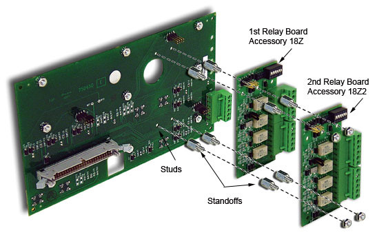
Conventional neutral switching pole. Note: Specify neutral option in catalog number, see ordering information page for instructions. Communications Options 72ASerial communication module for remote communications to ASCO PowerQuest® or SiteWeb® products. Also allows 4000 Series Transfer Switches to communicate via Modbus/RTU. 72EEthernet connectivity module for remote communications to ASCO PowerQuest® or SiteWeb® products. Contains embedded web pages for the remote monitoring of ASCO products, as well as some 3rd party devices. Also, provides Serial-to-Ethernet link with the ability to communicate using Modbus/TCP. Customer Control Circuits 30ALoad-shedding circuit initiated by opening of a customer-supplied contact. 30BLoad-shedding circuit initiated by removal of the customer-supplied control voltage. (Specify voltage). Add-on Boards 18ZIncludes one Form C contact (Rated 2A @ 30VDC or.5A@ 125VAC) for each of the following: - Normal Source Acceptability.
- Emergency Source Acceptability.
- Selective Load Disconnect. - Pre and post transfer signal time delay for selective load disconnect with a programmable bypass on source failures - adjustable 0 to 5 minutes.
- Fourth contact can be set to mimic the acceptability contacts or annunciate any combination of the acceptability contacts and/or any switch alarm conditions available:
- Extended Parallel Time (Closed transition),
- Failure to Synchronize (Closed transition),
- Transfer Switch Locked Out (Closed transition),
- Load Disconnected (Delayed transition).
- Accessory 18Z includes an extension of the engine start time delay (feature) to 60 seconds if an external 24VDC supply is connected to a 4000 series controller. This external power source will also allow the LCD display to be active when both normal and emergency sources are unavailable.
18Z2Includes two 18Z accessory boards. (Maximum of two 18Z accessory boards allowed.) 
-
This product does not have designated product packages.
Please see the Priced Options tab and select the options you want supplied with the product. Prices will update automatically when you select or remove an option.
-
Purchase option only
-
Standard FeaturesSeries 4000, Industrial Automatic & Manual Transfer Switches, Enclosed & Open with Open, Closed, and Delayed TransitionsClose differential 3 phase under-voltage sensing of Source1 (normal) - factory standard setting 90% pickup, 80% dropout (adjustable); under-frequency sensing of Source 1 factory setting 95% pickup (adjustable).Contact transfer speed less than 100 millisecondseTemperature rise test per UL 1008 conducted after overload and endurance tests in unventilated enclosure-exceeds UL requirementsHigh close-in and withstand capabilityNEMA Type 1 enclosure is standard. Also available in NEMA 3R, 4, 4X & 12.Voltage and frequency sensing of the Source 2 (emergency) - factory standard setting 90% pickup voltage, 95% pickup frequency (adjustable).Indicating LEDs for source availability and switch position.Pushbuttons for test, exerciser set, timer bypass and program cancel.Special status annunciation of in-phase transfer and timer operation.Selectable 7, 14, 21 or 28 day (factory set 28 dsays) generator (source2) with or without load exerciser timer.Diagnostic LED indications in logical one-line configuration.Auxiliary contacts (1 each) cclosed in Source 1 (normal) and Source 2 (emergency positions.Close differential under-voltage sensing of the normal source.Voltage and frequency sensing of the emergency source.Test switch (fast test/load/no load) to simulate normal source failure - automatically bypassed should the emergency source fail .Double throw, interlocked operation .Electrically operated, mechanically held by a simple, over-center mechanism.Segmented silver tungsten alloy contacts with separate arcing contacts on 600 amps and above.Arc quenching grids, enclosed arc chambers and wide contact air gap for superior source-to-source isolation on all units.Control circuit disconnect plug and drive inhibit switch for safe maintenance.Components accessible for inspection and maintenance without removal of the switch or the power conductors.Mechanical indicator and contact chamber cover designed for inspection, safety and position designation.
-
To get started with a lease, click the button below.
-
To see a list of generators in each category CLICK on these links.All Industrial, GeneratorJoe, Diesel, Single phase ~~~ All Industrial, GeneratorJoe, Diesel, Three phaseAll Industrial, GeneratorJoe, Gaseous, Single phase ~~~ All Industrial, GeneratorJoe, Gaseous, Three phase
-
To search for other products click the button below.
-
To find transfer switches click the button below.


